Electrical Heating of MIDREX® Process Gases
INTRODUCTION
The iron and steelmaking industry is experiencing rapid market change and technology developments. One of the key drivers for the market change is the need to improve the environmental impact of the processing routes. The reduction of CO2 emissions is one of the most important environmental goals facing the industry.
The Direct Reduction (DR) – Electric Arc Furnace (EAF) route is one of the most promising technologies to achieve the CO2 reductions. In order to achieve the reduction, the DR plants are extending their fuel options to include green hydrogen.
Hydrogen has great promise for the direct avoidance of CO2 from the DR route when used as the process fuel; however, hydrogen has drawbacks when applied as a fuel for heating the process gas in the conventional combustion-based heating unit operation.
Generally, green hydrogen is produced from electrolysis. If hydrogen is used as a fuel in a combustion system, then it can reduce the CO2 emission compared to a typical fossil-based fuel. However, inefficiencies are introduced when electricity is used to produce hydrogen, which must then be transported to the facility. In order to overcome the inefficiencies, it is advantageous to use electricity to directly heat the process gas.
An electric heater works by passing electricity through an element made of resistive wire. As current passes through the wire, it generates heat which is transferred to the medium being heated. The medium can vary from air and other inert gases to syngas, hydrogen, liquids, and steam. Electric heaters are used in many industries with various applications. Pressures greater than 200 bar and temperatures greater than 1,000° C can be achieved with thermal efficiencies greater than 95%. Power ratings can range from several hundred watts to several hundred megawatts, as the technology is extremely scalable.
As total system power requirements increase, typically the number of heaters increases as well. Depending on the pressure of the system, it is feasible to have a single heater capable of greater than 10 megawatts arranged in parallel with as many heaters as necessary to reach the system power requirement. Each of these heaters is controlled via a control panel using closed loop feedback with built in protection in case of a low or no flow condition or any condition where the element wire temperature might exceed the design limit.
Considering that direct electric heating is already demonstrated at the required scale, then it remains to demonstrate the performance in the field of heating process gases for a MIDREX® Plant.
This article will address the current state-of-the-art for electric heating of gases for DR applications, and development work on thermal cycling of electric heaters in the DR application.
DISCUSSION
There are several operating conditions of importance when considering the design of an electric process gas heater for a MIDREX H2™ Plant. The focus of this article is the thermal cycling of the electric heater.
A state-of-the-art MIDREX Plant will normally operate in excess of 8,000 hours per year. The balance of the operating time is a combination of scheduled maintenance and unscheduled plant stoppages. The concern associated with these stoppages is due to the nature of the materials and normal operating temperature.
Figure 1 shows the flows in a MIDREX H2 Plant that incorporates an electric heater (CO2-Free Gas Heater). The stream identified as 1 corresponds to the hot reducing gas that is to be introduced to the shaft furnace. The exact requirement of Stream 1 depends on the application; however, for industrially relevant examples it is most common to find temperatures of more than 900 degrees C. At these elevated temperatures, the mechanical properties of the metal components become of interest. When a heating unit operation is shutdown from normal operating temperature to ambient temperature, it is referred to as a ‘thermal cycle’.
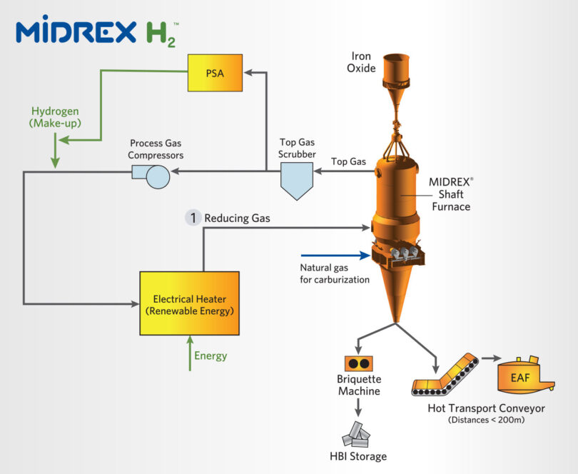
FIGURE 1.
Process Flow Diagram for DRI Production using Hydrogen
Thermal cycling can be observed in the various alloy reformer tubes and heater tubes from the traditional natural gas-based direct reduction technologies. From these references it is readily observed that thermal cycling is generally a negative factor to the overall life of the components. Thermal cycling can result in changes in the equipment geometry due to thermal expansion of the components, possible microstructure changes, or other stresses on the material related to operating the components near to their operating limits and then rapidly changing the condition.
Since the possibility to have these shutdown is related to areas of the MIDREX H2 technology outside of the heater unit itself, then we should assume that the electric heater will be subjected to similar conditions as the conventional reformer and heater unit operations.
In order to investigate this phenomenon, an experiment was run to measure the effect on an electric heating element over the course of repeated thermal cycles.
TEST SETUP
The block flow diagram for the test apparatus is shown in Figure 2.
Figure 2 shows a gas recycle and conditioning loop that is designed to supply an electric heater with a gas flow similar to what is required for the normal operating condition of a hydrogen-based MIDREX Plant.
The loop includes:
- An electric heater that is the subject of investigation
- A recycle loop consisting of a gas cooler, recycle compressor, and preheater
- A make-up gas skid to control the gas composition
- A system pressure control, and flare
- A gas analysis system and various other instrumentation
The fundamental test concept was to operate the electric heater with a suitably high exit gas temperature, and then simulate an unexpected plant stoppage by simply turning the electric heater off. The procedure was repeated 50 times and the heater element was inspected after the trial. Considering that a typical MIDREX Plant will experience a cold shutdown event between three and five times per year, the 50 cycles represent between 10 and 15 years of plant operating conditions.
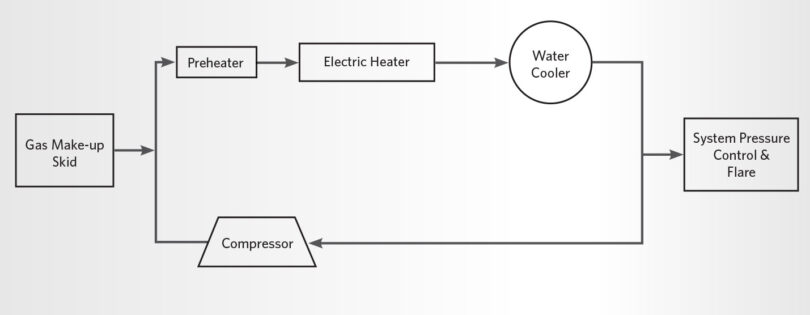
FIGURE 2.
Block Flow Diagram of the Test Apparatus
RESULTS
Figures 3 and 4 show the gas inlet temperature and gas outlet temperature, as measured in the testing apparatus. Figure 3 shows the data from the initial series of thermal cycles and 4 shows the data from the final series of thermal cycles.
The operation shows that the gas temperature was heated up at a controlled rate, kept at the target temperature for a short period, and then abruptly cycled. The final cycles show no difference in the operation compared to the initial cycles. In Figure 4 the final peak does not reach to 1,000 deg C because that is the 51st cycle and the test was stopped.
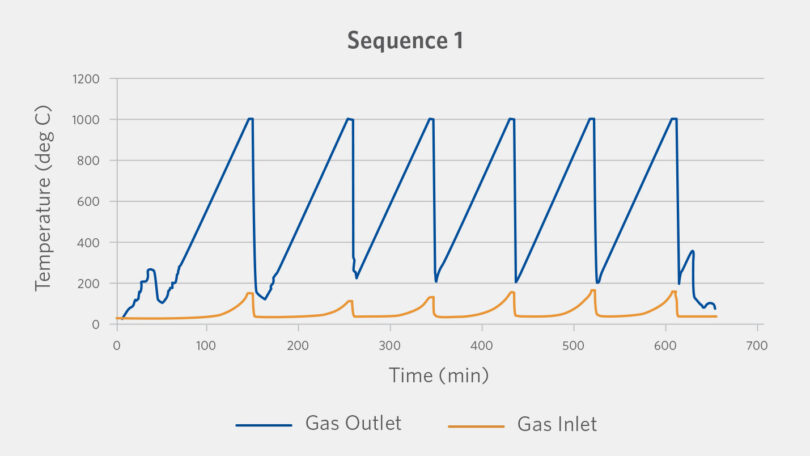
FIGURE 3.
Thermal Cycling Test showing the Gas Inlet and Outlet Temperatures for the initial operation
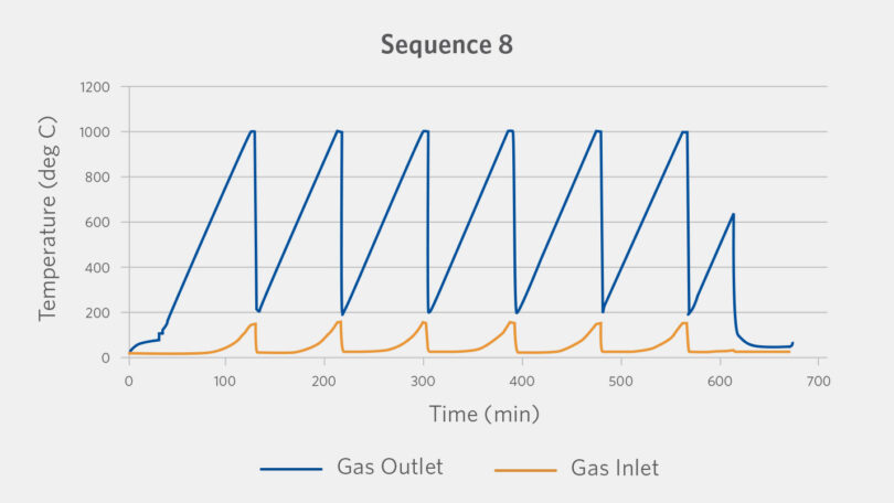
FIGURE 4.
Thermal Cycling Test showing the Gas Inlet and Outlet Temperatures for the final operation
Figures 5 and 6 show the measured electrical current and voltage corresponding to the same thermal cycles shown in Figure 3 and 4. The electrical response of the heater is consistent across the 50 thermal cycles. This indicates that there is no change in the electric heater’s electrical properties.
Figures 5 and 6 also indicate that there was no mechanical failure that would cause a change in the heater electrical resistance or performance.
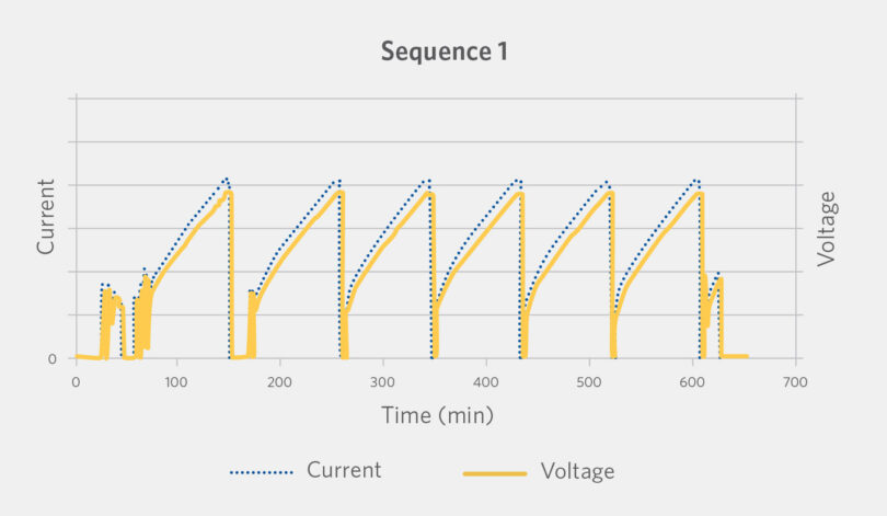
FIGURE 5.
Thermal Cycling Test showing the heater current and voltage for the initial operation
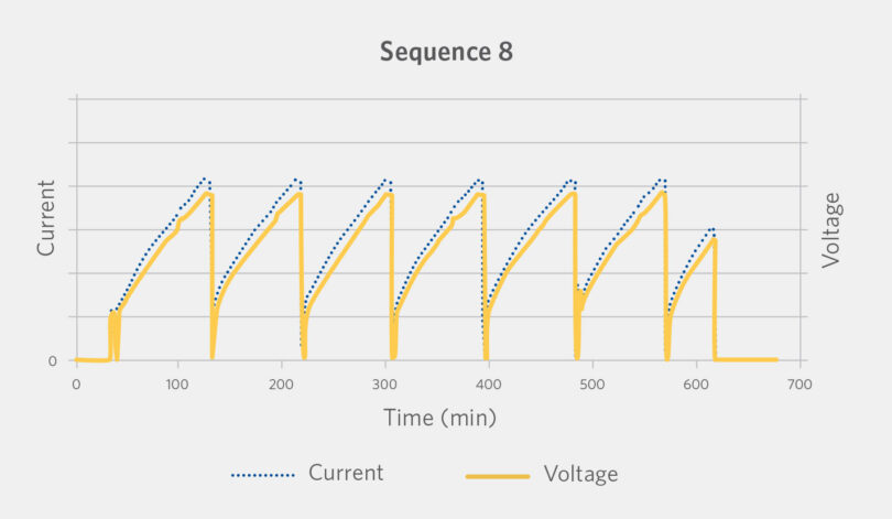
FIGURE 6.
Thermal Cycling Test showing the heater current and voltage for the final operation
CONCLUSION
An electrical heater was tested for thermal cycling under gas compositions and temperatures relevant to the direct reduction of iron for hydrogen-based operating conditions. The number of thermal cycles that were demonstrated is consistent with the number of cycles expected for between 10 and 15 years of plant operation. There was no observed change in the electrical heater performance or electrical properties over the 50 thermal cycles.
(This article is based on a paper presented at METEC 2023 & 6th ESTAD in Duesseldorf, Germany)


